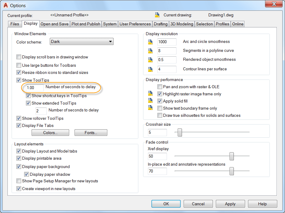
AutoCAD has had 2D geometric and dimensional constraints for a while, but most drafters don’t leverage their functionality in everyday use. I sometimes think it is because they can’t think of an everyday use for them. In this post, let’s look at a real-world example of using constraints that really saves you a good bit of time and automates a workflow that aids you in designing. (And be sure to check out my TuesdayTipsarticle with an overview of 2D constraints.)
Contents
Borehole Construction
The specific example I will cover here is for constructing utilities under a major road or highway where we cannot dig a trench due to the high volume of traffic on the road. Instead, we will propose borehole construction which will dig a hole underneath the road using a casing pipe that will carry the utility pipe. The diagram below shows the design standards that we must follow for this project
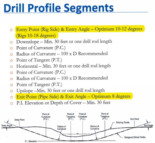
So, looking at the diagram, we can see that the standards call for a range of deflection angles for the entrance and exit of the pipe. Note though that the entrance and exit can be swapped based upon the existing conditions on either side of the road. Now, in an “orthogonal” world, this wouldn’t be that difficult as you could simply have a block that has these deflection angles. But, in the real world, the existing ground will vary, the depth to the pipe will need to be adjusted, and the deflection angle will need to follow this adjustment. 2D geometric and dimensional constraints to the rescue.
Drawing the Criteria
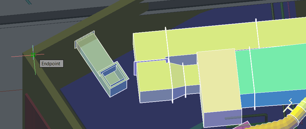
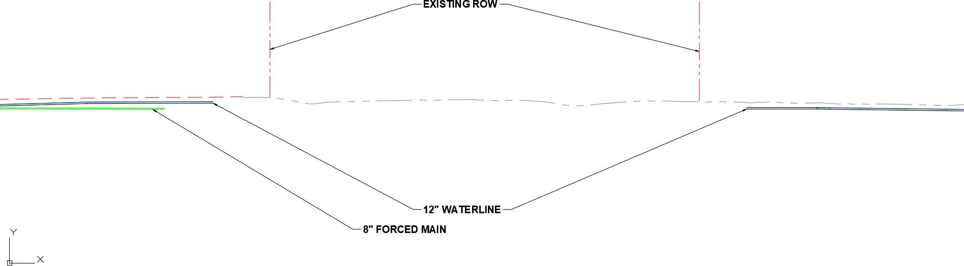
Below is our area of design. I have a profile view (cut with Civil3D) at a scale of 1:1 so that we can design this without having to worry about an exaggerated scale.
The first thing I’ll do is to draw the basic geometric components as it really doesn’t matter how they are initially drawn because the constraints will “fix” the geometry for me.
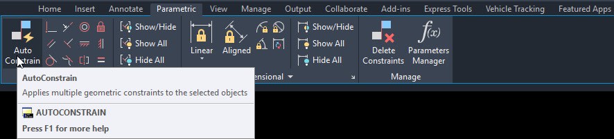
Use the AUTOCONSTRAIN tool to automatically constrain the geometry.
Now since I don’t always have “flat” ground, I’m going to delete the horizontal and perpendicular constraints.
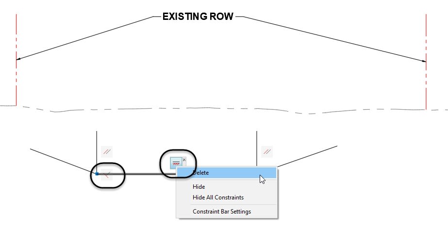
To finalize the geometric constraints, I will add a vertical constraint to one of the vertical lines as there is already a parallel constraint associated to the two lines.
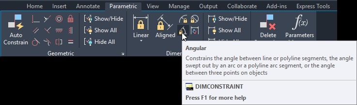
 Now, we will need to add the geometric constraints to add the appropriate angle of deflection on either side. Navigate to the Dimensional panel in the Parametric tab and add an angular dimensional constraint.
Now, you want to select the vertical line first and then the adjacent line, and define an angle of 78 (90-12).
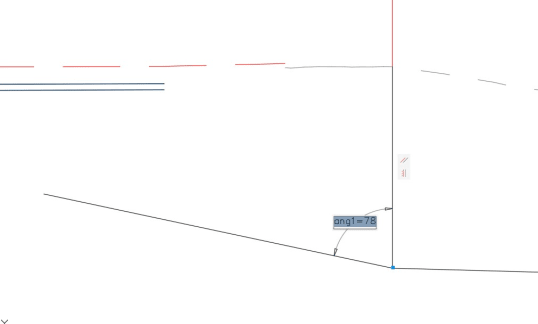
And add one to the other side for a value of 82 (90-8).

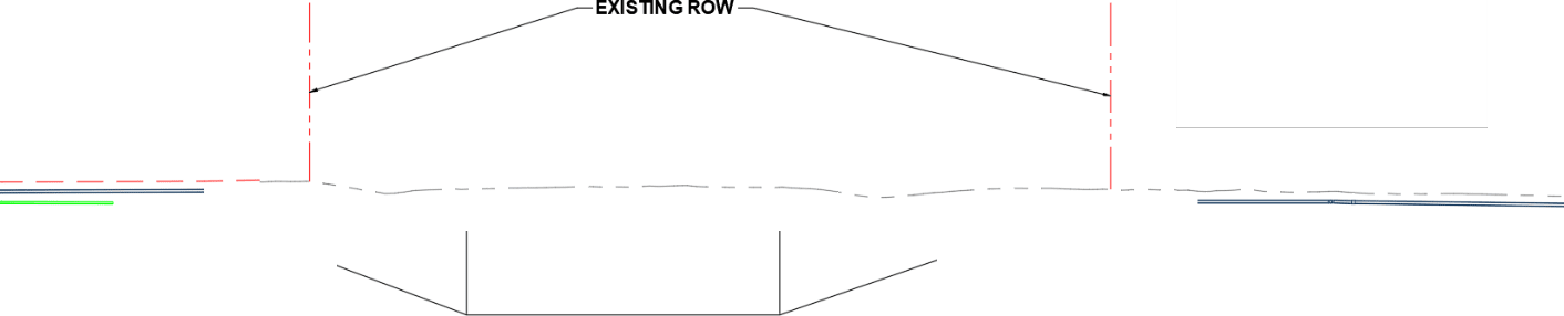
Now, we can position our lines to the correct location in the profile to see where the entrance and exit pipes will go. Some little tricks to working with the geometry are listed below:
- Use the STRETCH command – Sometimes grip editing or moving will not work when trying to get the geometry into the correct position. Don’t forget to use a crossing window when stretching.
- You can use grip-editing (sometimes) – Grip-editing can be used to modify your geometry. However, sometimes it will “break” the constraints if you do. When using grip-editing, and you want to define a total length for a line, pick the Length option from the multi-functional grip menu…..

Press TAB on the keyboard to access the total length field and type in a distance.

This workflow will maintain the constraints.
Now with my geometry in the right location, I can stretch the line and see where my pipe location will enter/exit.

Don’t forget, the cool thing about the angular constraints is that you can change them as you need it. Remember, the detail doesn’t say which side has to be the entrance/exit.
I hope this real-world example makes your brain think of many other uses of using 2D constraints.
Source: Autodesk