You can use inserted or linked AutoCAD data within a Revit model as an underlay, and then model building objects such as walls, doors, and windows by either tracing over the lines or by using the Pick Lines option.
In this model, a two-dimensional AutoCAD floor plan of an existing building has been linked. You can use that file as an underlay to build Revit geometry. On the Manage ribbon, in the Manage Project panel, click Manage Links.
Revit displays the Manage Links dialog. On the CAD Formats tab, you can see that there is a linked AutoCAD DWG file. The dialog shows the name of the Linked File, its Status, its file Size, its Saved Path, and its Path Type.
When you select the linked file, the other tools become active. You could click Save Positions to save the position of the file relative to the shared coordinate system in the host project. You can also Reload the linked file, Unload the linked file, change it from a linked file to an imported file, or remove the link from the project.
Also, pay attention to Preserve graphic overrides. Select this option if you want to retain any graphic overrides. Click Cancel to close the dialog.
When you select the AutoCAD file, Revit displays a contextual ribbon, including draw order tools to move the linked file to the back or bring it to the front. There are also tools to Delete Layers or Query the file.
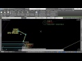
Click Query. Then zoom in on the upper-left corner of the floor plan and select one of the teal lines in the interior of the wall. Revit displays the Import Instance Query dialog, which displays information about the object you just selected, including the name of the layer on which that line was drawn.
At this point, you can hide that layer in the current view or delete the layer from Revit. Click Hide in View. After you do, the Query tool remains active.
Select another line inside the wall. Again, Revit displays the Import Instance Query dialog and shows you that this line is on the A-Wall-Patt layer. This time, click Delete. Deleting layers will not affect the original AutoCAD drawing file, even though the file is linked. The layer is simply deleted from the Revit project.
Now that the visual representation has been simplified, you are ready to start placing Revit walls.
If you want to match the thickness of the walls in the AutoCAD file, you can measure them to determine their thickness. On the Quick Access Toolbar, click Measure Between Two References, you may need to zoom in a bit, and measure the thickness of the wall. Do this by clicking on the right wall line, then the left wall line.
To place Revit walls over the AutoCAD file, from the Architecture ribbon, in the Build panel, start the Wall tool. On the Options bar, set the Location Line to Finish Face: Exterior and make sure that Chain is selected. In the Type Selector, you should choose an appropriate wall type that matches the thickness of the wall.
For this example, leave the type set to Generic – 8″ (or Generic – 200 mm Wall in the metric file). Remember that when placing walls, if you work in a clockwise direction, the exterior face of the wall will face the outside of the building. Also, Revit will automatically find the center of two closely spaced parallel lines. This is beneficial when placing walls or other elements along the centerline of walls.
Zoom out so you can see the entire floorplan.
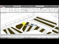
Click the exterior corner at the upper left to begin placing walls. Work your way clockwise around the perimeter of the building, clicking each time to add a new corner, eventually you should make it back to the starting point. Be careful when placing the walls, but you can always make minor changes to corner placement later.
Once the outer walls are done, to place interior walls, expand the Type Selector and choose Generic- 5″ (or Interior – Stud Steel 90 in the metric file).
In the Draw panel, choose Pick Lines. On the Options bar, ensure the Location Line is set to Finish Face: Exterior. Then, starting at the upper left, click to begin placing the corridor walls based on the AutoCAD file interior walls.
If you place a wall in the wrong location, you can use the flip control to correct its placement.
Place a few more walls.
You can use the trim tools to clean up the wall intersections. For example, use Trim/Extend to Corner to extend the corridor walls to each other. You can also use Trim/Extend Multiple Elements to extend walls to other interior or exterior walls.
Click Modify to end the command when you are finished.
Next, you can place doors at the proper locations. To do this, you may want to move the AutoCAD file to the foreground. Select the AutoCAD floorplan, Then, in either the Properties palette or on the Options bar, change the Draw Layer to Foreground, then click in an empty spot to deselect the floorplan.
Now you can more easily see where to place doors. Note that the ability to move the floorplan to the background or foreground is only available when working with a 2D file. When you link or import an AutoCAD file, you can flatten it to 2D by choosing Current view only.
If the file is 3D, you can also change the Visual Style to Wireframe to more easily see where to insert doors and windows. From the Architecture ribbon, in the Build panel, start the Door tool.
Remember that doors are hosted by walls, so you must move the cursor over a Revit wall. Click to place a door. If you do not place a door in the correct location, you can use the Align tool to match the door to the underlying geometry.
Source: Autodesk