Creating 3D Objects by Extruding 2D Objects
The Extrude tool creates a 3D solid or surface by extruding a 2D object. In most cases, if you extrude an open curve, the result is a surface. If you extrude a closed curve, the result is either a solid or a surface, depending on the current mode. Also note that when extruding to create a surface, you can control whether the surface is a NURBS surface or a procedural surface. When creating a procedural surface, you can also control whether the resulting surface is associative. When you create an associative surface, if you subsequently modify the original curve, the resulting surface automatically updates.
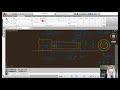
To start the command, on the Home ribbon, in the Modeling panel, expand the split button and click the Extrude tool. This same tool is also available on the Solid ribbon in the Solid panel. The program prompts you to select an object to extrude, and you can use any object selection method. You can also right-click and choose the Mode option. When extruding a closed profile, you can control whether the resulting object will be a solid or a surface. Choose Solid. Then, click to select the object you want to extrude and then press ENTER.
The program then prompts you to specify the height of extrusion, or you can choose one of the other options. Enter an extrusion height of 8 units and press ENTER. When you simply specify a height, the program extrudes the selected objects to the height you specify, and the command ends. Since you chose the Solid mode option and the object being extruded was a closed polyline, the resulting object is a 3D solid.
Start the command again, select an open polyline, press ENTER, and then specify an extrusion height of 8 units. This time, because the original object was an open polyline, the resulting object is a surface. By default, that surface is a procedural surface, which means that it is associative with the original curve. If you modify the original polyline, the surface immediately updates to reflect those changes.
Start the command again, select the object you want to extrude, such as a circle, and then press ENTER. Then, right-click and choose the Direction option. The program prompts you to specify the start point of direction. Click to pick a point. The program then prompts you to specify the end point of direction. The vector between those two points determines the extrusion direction and the height of the extrusion.
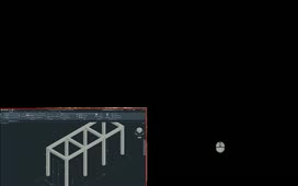
Start the command again, select the object you want to extrude, and then press ENTER. Then, right-click and choose the Path option. The program prompts you to select the extrusion path. Click to select the object that represents the path along which you want to extrude the object. The path does not have to be in the same location as the object being extruded. Just make sure that the path is not on the same plane as the object.
Start the command again, select the object you want to extrude, and then press ENTER. Then, right-click and choose the Taper angle option. The program prompts you to specify the angle of taper for the extrusion. Positive angles taper in from the base object; negative values taper out. The default value of 0 extrudes the object perpendicular to the XY-plane. Enter a taper angle of 7 degrees. After specifying the taper angle, you can specify the height of the extrusion, or use any of the other options.
In fact, most of the options remain available so that they can be combined. For example, start the command again and select the object to be extruded. Then, right-click, choose Mode, and then select Surface. Then, right-click and choose Taper angle. Specify a taper angle of 4 degrees and press ENTER. Then, right-click again and choose the Path option. When you are prompted to select the extrusion path, click to select the adjacent polyline. As soon as you do, the circle is extruded along the path and its diameter tapers at a 4-degree angle. And since by default surfaces remain associative to the curves used to create them, if you modify either the circle or the path, the resulting surface immediately updates to reflect those changes.
The Extrude command offers all sorts of interesting possibilities for creating solids and surfaces.
Source: Autodesk