You can edit associative center marks and centerlines by using grips or tools in the Properties palette. While you can use various system variables to control the appearance and behavior of a centerline or center mark, once created, it is usually easier to modify its appearance by using grips or the Properties palette.
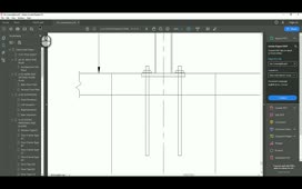
For example, the exercise file shows two views of a mechanical part to which several centerlines and center marks have already been applied.
In the cross section view on the left, select the centerline through the central axis of the part, and then zoom in. When you do, you can clearly see five grips. The square grip at the midpoint of the line is the center grip. If you were to make this the hot grip and then move the centerline, it would no longer be associated with the geometry.
The square grips at either end of the centerline are its length grips. Their location corresponds to the length of the lines to which the centerline is associated. The triangular grips at the ends of the centerlines are the overshoot grips. The distance between the length grip and the overshoot grip is initially determined by the CENTEREXE system variable, and the same overshoot is applied at both ends of the centerline. Once the centerline has been created, you can change the overshoot separately for either end of the centerline, by either moving the triangular grip or by using the Properties palette.
For example, click the square grip at the left end of the centerline and then drag it to the left to lengthen the centerline. When you move the square grip, the triangular overshoot grip moves along with it. Note that as you move the grip, you can specify the precise length of the centerline, measured from its center grip.
With the centerline still selected, expand the Properties palette. Under General, you can see properties such as the layer on which the centerline was drawn and its linetype. These values were initially determined by system variables, but can be modified here once the centerline has been created. Under Geometry, you can see the coordinates of the start and end points of the centerline, but you cannot change them. Those values can only be modified by dragging the square location grips. You can change the Start extension and End extension values, however.
In the drawing, click to select the triangular grip at the right end of the centerline and begin to drag it to the right. When you see the length field, type “1.25” and press ENTER. Go back to the Properties palette and note that the Start extension value now matches the extension length you just typed.
Press ESC to deselect the centerline. Then zoom out so that you can once again see the entire drawing. Then, in the view on the right, zoom in on the central circle and select the center mark.
When you select a center mark, both portions of the center mark highlight, and you see multiple square and triangular grips. The square grip at the center is the center grip. If you were to make this the hot grip and then move the center mark, it would no longer be associated with the circle.
In the Properties palette, under General, you again see properties such Layer and Linetype, which can easily be modified. Under Geometry, you see many more fields, all of which can be changed. For example, you can change the size of the cross at the center of the center mark, the gap between the cross and the extension line, and the individual extension or overshoot lengths at the left, right, top, and bottom of the center mark. Note that these are all currently set to 0.1200 units, the value determined by the CENTEREXE system variable when the center mark was created. There is also a control to toggle the display of the extension lines. Click in the Show extension field, expand the drop-down, and choose No. The center mark now only shows the cross at its center. Expand this drop-down and select Yes so that you once again see the extension lines.
When you hover the cursor over the square center grip, you see an extended tooltip. If you were to choose Stretch, you would move the center mark, thus disassociating it. When you select Change Extension Length, however, the program prompts you to specify an extension length for all four sides, and in the drawing you can see that all four ends of the center mark extend equally as you move the cursor. You can also type a new extension. Type “0.5” and press ENTER. The center mark immediately updates. With the center mark still selected, go back to the Properties palette and note that all four extension values have changed to match the extension length you just entered.
In the drawing, click and drag the triangular grip at the left end of the center mark and make it approximately 3 units long. Then, expand the Properties palette again. You can see that the Left extension value has changed.
Click to select the square grip at the right end of the center mark and then drag it to the right approximately 3 units. In the Properties palette, note that the Right extension value has not changed, because you changed the length of the extension line, not its overshoot.
When you change the length of the extension line rather than the overshoot distance, that particular extension line becomes a fixed length and does not remain associated to the circle. To see this, press ESC to deselect the center mark. Then, select the circle, click to select one of its quadrant grips, and then drag it to change the size of the circle. The left, top, and bottom extension lines change, but the extension line on the right remains the length that you specified by dragging its grip.
Press ESC to deselect the circle and then select the center mark again. In the Properties palette, under Geometry, click in the Cross gap field and change the value from 0.05x to 0.25x. As soon as you do, the gap between the center cross and the extension lines changes. Change this back to 0.05x.
Note that the Cross size and Cross gap values are determined by the CENTERCROSSSIZE and CENTERCROSSGAP system variables, respectively. These values are related to one another and can be specified using absolute values, relative values (by including the “x”), or based on the linetype used for creating the center mark. Both values should use the same value type.
In the Properties palette, under Misc, you can also modify the Rotation angle of center marks. Press ESC to deselect the center mark.
If you have changed the lengths of extension lines, you can reset the extension lines of a center mark or centerline to the current value specified in the CENTEREXE system variable. First, type the system variable “CENTEREXE” and press ENTER. The program prompts you to enter a new value and shows you the current value. Type “0.25” and press ENTER.
Next, to reset the extension lines a centerline or center mark, type CENTERRESET and press ENTER. The program prompts you to select a center mark or centerline. Click to select the center mark. The prompt repeats so that you can select another centerline or center mark. Click to select another center mark and the press ENTER. Both center marks immediately adjust to reflect the new extension line value. You can use this command to quickly change the size of multiple centerlines and center marks. But again, the right extension line of the center mark on the right did not change, because when you dragged its square grip, you assigned it a fixed length.
Source: Autodesk