A year ago I wrote an article in English titled How to Dimension Silhouette Edges Using SOLIDWORKS MBD (How to Dimension Your Part Using Silhouette Edges Using SOLIDWORKS MBD). This technique is often used to define parts of revolution, such as grooves, cones, chamfers, shoulders or holes. Figure 1 below shows various examples of a detailed view of a tree.
Figure 1. Annotations using silhouette edges to define a chamfer or groove.
This post sparked an interesting discussion about the nature of a 3D drawing and a model-based definition (MBD). I would therefore like to add a few details in this post. In my opinion, to meet various use cases, implementations of MBD require multiple phases. 3D drawing is an initial stage to meet the needs of 3D visual representation, but remains far from the true potential of MBD.
A 3D drawing follows the principles of 2D representation. It simply converts 2D annotations to a 3D model, as in Figure 1 (above). Due to conventions inherited from 2D, 3D drawings may be easier to adopt initially. They usually define geometric features, such as edges, curves, and vertices in detail, instead of defining elements such as faces, holes, slots, and pockets. Geometric definitions limit the potential for downstream manufacturing automation, due to lack of functionality.
Therefore, in order to better meet the needs of the manufacturing processes, we can recommend definitions based on functionalities, because in the workshop, it is the faces, holes, grooves and pockets that are the object of machining and inspection. . Edges, curves and vertices are just the result of these features. No operator will be interested in the distance between two points or curves. What matters to him is the diameter of a cylinder or the distance between two faces.
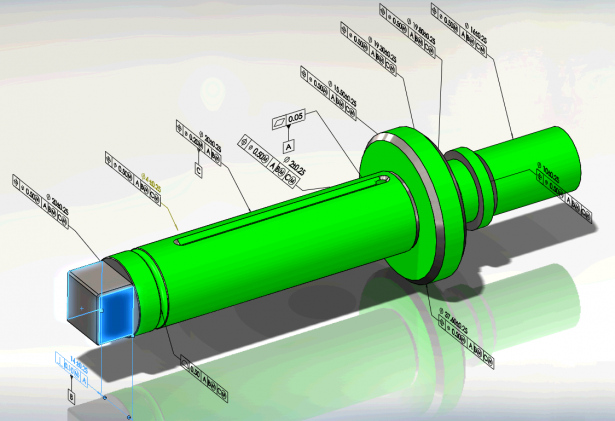
In addition, 3D digital models allow particular implementations of the MBD, which go beyond the horizons of the drawing. Thus, feature annotation enables consistent application of geometric tolerances and cross-highlighting between annotations and defined features. Figure 2 shows the tolerance factor for different faces in green, to indicate that they are fully tolerated. Also, the width as a B reference feature is highlighted in blue when the annotation is selected. These intelligent 3D annotations can be viewed visually, but also analyzed by a program and taken into account by downstream manufacturing software applications, such as computer aided manufacturing (CAM) or a coordinate measuring machine (CMM). Automation is the main advantage of MBD.
 Figure 2. Model annotated with smart symbols of geometric tolerances.
To conclude, let’s return to the various needs of model-based modeling implementations. If you’re primarily looking to represent visual information in 3D in an intuitive way, 3D drawings are a good place to start. If you want to lay the foundation for downstream manufacturing automation, it is advisable to use semantic, function-based definitions.
As a software developer, SOLIDWORKS offers both options, in order to cover a number of needs. So, reference dimensions work similarly to 2D detail tools, which can help you with 3D drawing tasks. On the other hand, DimXpert closely follows the ASME Y14.5 geometric tolerance standard and ASME Y14.41 product definition standard, giving you better support from defining product specifications to automating manufacturing.
To learn more about SOLIDWORKS MBD, I invite you to watch the 22 minute webcast below and consult the product page. You can also chat with me on Twitter (@OboeWu) Where LinkedIn (OboeWu).