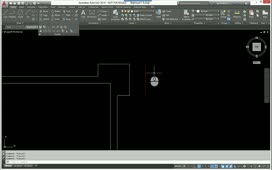
Polar tracking restricts cursor movement to specified angles. Typically, you use incremental angles, such as 45, 90, 135, 180, and so on. But you can also add specific angles.
To control the polar angle settings, on the Status bar, click the arrow to the right of the polar tracking button and choose Tracking Settings… to open the Drafting Settings dialog.
In the Polar Angle Settings group box, you can expand the Incremental angle drop-down list and select one of the standard values. When you select one of these angles, the program will lock the polar alignment to increments of the angle you select. For example, if you select 45, the polar alignment will snap to increments of 45 degrees, including 0, 45, 90, 135, 180 degrees, and so on.
If you want to use an incremental angle other than one of the angles shown in the list, you can simply type the incremental angle value into the field at the top of the drop-down. For example, to use an incremental angle of 25 degrees, type 25 into the field. Then, click OK to close the dialog.
Make sure that polar tracking is on and then start the LINE command. Click to specify the first point of the line. When the program prompts you to specify the next point and you move the cursor, it now snaps to polar tracking alignment angles of 0, 25 degrees, 50 degrees, and 75 degrees. Then it skips 90 degrees, because 90 is not an increment of 25 degrees, and then snaps to the next alignment angle of 100 degrees, and to each successive increment of 25 degrees.
Press ESC to cancel the command. Then click the arrow on the Status bar to view the polar tracking menu. Notice that the angle of 25 degrees was not added to the shortcut menu. This menu only shows the standard angle increments. Also note that 23 actually represents the 22.5-degree increment. Click Tracking Settings… to go back to the Drafting Settings dialog. Expand the Increment angle drop-down. The 25-degree increment angle you added does appear in this list.
In most cases, you will probably use one of the standard incremental angles, because those are the most common angles. Choose 45 degrees.
There may be times, however, when you do want to snap to a very specific angle. Perhaps in addition to the standard 45-degree angle increments, you want to be able to snap to an angle of 25 degrees. You can add additional angles. Click the New button, then type 25, and press ENTER to add 25 degrees as an additional angle. Click New again, type 75 and press ENTER. Then, click OK to close the dialog.
Now, start the LINE command, click to specify the first point of the line, and then move the cursor. Notice that now, you can select polar alignments of 0, the additional angle of 25 degrees, the incremental angle of 45 degrees, the additional angle of 75 degrees, and the incremental angle of 90 degrees. Then it continues to snap at incremental angles of 135 degrees, 180 degrees, and so on.
So not only can you change the incremental angle and even add your own incremental angle values, you can also add specific angles so that you can use polar tracking to align with the angles you specify.
Source: Autodesk


