Labels can be created in Civil 3D to annotate objects or plain AutoCAD linework. The display of these labels is controlled by the label style for the object. You can find the label styles in the Toolspace, Settings tab, under any object collection. For example, expand Alignments, and then expand Label Styles. Expand Station, expand Major Station and then select the label style Parallel with Tick. Right-click that and select Edit, and the Label Style Composer opens.
The Label Style Composer within Civil 3D is the only dialog box you will see when creating and editing label styles. This dialog box always has an Information tab, a General tab, a Layout tab, a tab for the Dragged State, and a Summary tab, no matter which object label style you are creating or editing. Once you become familiar with this interface in one object style, you will use it over and over again with different objects throughout Civil 3D. So it is important to understand everything in this dialog box.
The Information tab is very simple. Here, you can enter both a name and a description for the Label Style. It also has information about who created the Label Style, when it was created, when it was last modified, and by whom.
The General tab allows you to select a default text style for this label style. You can also control the label visibility and the layer that the label is created on. If you place a label on Layer 0 in this tab, then the labels will acquire all the layer properties of the layer that the label is placed on, such as the layer color or the layer linetype.
In the Behavior section, you can choose if the label references an object, a view, or the world coordinate system. Most of the time, you will set this to either Object or View. Under Plan Readability, you can select if the label will be plan-readable, and at what angle the will flip to maintain the Plan Readability Bias. To understand this more click Cancel to exit out of the dialog box and switch to the Plan Readable Bias drawing.
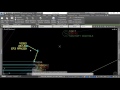
Here, you can see some text at different angles, and typically you want your text to be plan readable, meaning that when the plan is read right-side up, all of the text is easily readable without having to turn your head or rotate the drawing. When you use the Plan Readable option in the Label Style Composer, Civil 3D automatically flips over the text once it goes past the set angle in the dialog box. In this case, the default is at 110°, so text would stay oriented in its current direction up to 90° and even past 90° to 110°. Once the angle is past 110°, it flips over to be Plan Readable in the other direction. That Plan Readability Bias is the angle that you can set here, so if you want that text to flip at 90°, you would set the Plan Readability Bias to 90 or 92 if the text is flipping too early in your opinion.
Switch back to the first exercise drawing, and in the Toolspace, Settings tab, under Alignments and Label Styles, re-open the Parallel with Tick label style, and then right-click and select Edit. Back in the Label Style Composer, on the General tab is that Plan Readability Bias setting.
Click the Layout tab.
This is where you will do the majority of your work configuring and setting up the label style. The Component name drop-down has a list of components. Select one, and all the properties of that component are displayed in the pane below. For instance, under General, next to Name you can type in any name you choose to place here. You can also control whether this part of the label is visible or not, as well as which component this part of the label is anchored to. In this case, it is anchored to the Feature. Components within the label can be anchored to other components as well. You can also control the Anchor Point on the Anchor Component.
What is a component? Components are what make up parts of the label. They can be text, reference text from another similar object, lines, blocks in your drawing and ticks. You can find a quick drop-down list of components to use or add to your label just to the right of the component name drop-down. Click the down arrow of the Create Text Component button to see what is available to use. If you choose any one of these items, a new component is made in your label. From there, you will need to name it, attach it, and manipulate the fields to represent the data you want this component to represent.
Expand Text collection. You can determine the actual text contents and their scale and rotation in this area. Click in the value field next to Contents, and then click the ellipses button that appears. The Text Component Editor opens, which displays the properties in that particular label component. Right now, there is a Station Value. Click the Station Value in the Properties drop-down, and you can see a list of all of the other available properties that you can label.
To try this, add a text label item to your current label. First, in the black dialog box where you see the field for the station value text, click in this box. Move the cursor to the end of the field and add a space where the next field of text will go. You can add simple text by just typing, so add in the word “at” then a space after it.
Now you will add a new property field. Choose the Design Speed property from the Properties drop-down, and then configure the settings that appear below the properties pull down, such as the Unit and Precision. Change the Precision to 0.01. To get the new property into the label after making all the adjustments, you must do one last thing, click the Insert arrow.
The property field is inserted after the word at. You could keep on going, choosing properties, setting up their settings then clicking the insert arrow until you are happy with your label. It is also a similar method to modify an inserted field. Click the field you inserted for the Design speed. Highlight it blue, and then in the Settings dialogbox, change the precision from 0.01 to 1. Click the Insert arrow to update the field. The designator within the field changes to P0. P stands for Precision and the number after that stands for the designated value to use.
Remember until you click that Insert arrow, no changes you make in the settings or new properties you choose to enter will be added to your label. The procedure is almost always the same: click in the black box, select your field, edit your settings, click the Insert arrow and repeat. To see your new changes, click OK in the Text Component Editor.
Back in the Label Style Composer, in the Preview box on the right, you can see the change to the label. Click in the preview box, right-click and select Zoom. When the magnifier icon lights up, scroll in on the stationing text. You can now see the 0 mi/h added to the end of the station text and the word “at.”
Besides adding text, you can also set the Text Height. This is a plotted height that will be dependent upon your Annotation Scale, or the Viewport Scale if you are working in paper space. You can set a Rotation Angle for both the text and for the attachment point on the text so that the attachment point on the text will link to the anchor point on the anchor component. Scroll down in the list, and you can also add X and Y offsets, colors and even borders and background masks if you want.
Next, expand Component name to switch to a different component and configure all those values. Select Tick.
This component has less information here because it is simply inserting a block. You can determine the block height, its rotation, and color. You can also add line components, block components, and reference text. The Reference Text component would allow you to label data from other Civil 3D objects. For instance, along with stationing, you can add a surface elevation at those locations from a selected surface within your drawing.
The Dragged State tab allows you to configure the display of the label if you drag it away from its original location. Here, you can configure the setting so that a leader is drawn pointing back to the original location, and also configure how that text is displayed. Expand the drop-down next to Display, and there are two main options here for Stacked Text and As Composed. Stacked text allows you to apply new values from your original text setup. Under Layout, there are overriding options for when you drag out your text. Change the selection to As Composed, and now the options below are not selectable.
This is because As Composed forces the label to stay in the same state that it was set up in originally but dragged to a new location. Its options are configured according to those in the Layout tab.
On the Summary tab, you can see a summary of all of these values.
Expand the collections to see them, then click Cancel.
Different components can be linked to other components within the Label. To see this, open another label style. Expand Point, then Label Styles and select the Point# and Description label style. Right-click it and select Edit.
On the Layout tab, there are two components: Point Description and Point Number. Select Point Number and you can see that the Point Number in the preview, number 1 or 2, is using an Anchor Component of the Feature.
The Properties pane lists its Anchor Point as being the Middle Right of the Feature, which in this case is the point. The Text for the Point Number Component is attached at the Bottom left of the piece of text. So, the bottom left corner of this text is attached to the Middle Right of the Feature or the Point.
Now switch the component to the Point Description and you can see that the Point Description is actually anchored to the bottom left of the point number, rather than to the feature itself. So you can see by the attachment that the top left corner of the description is attached to the bottom left of the point number. This is how different components can be linked to other components within the label. Click Cancel.
Select the Settings tab. Here, you can see the hierarchy which allows you to apply overall changes to your label styles. Right-click the feature level, and select Edit Label Style Defaults. In the Edit Label Style Defaults dialog, you can set the Text Style, Behavior, Plan Readability, and even the properties of the components, such as text height and color. Any changes here would apply to all of the labels for that particular feature, unless you apply the Child Override.
If you want to make global changes to an entire drawing, select the top drawing level in the Toolspace, right-click over the bolded drawing name and select Edit Label Style Defaults.
The same options are available here, but these apply to the entire drawing, rather than to all the labels for one specific feature.
As you can see, Civil 3D gives you many options and ways to label objects and AutoCAD linework. By using label styles, you can change one label in one spot and that change will filter to all labels sharing that same style throughout your drawing.
Source: Autodesk