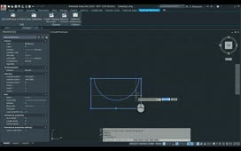
Presentations are used to develop scenes, exploded views, animations, and other stylized views of an assembly to aid you in documenting your design. Animations can then be used to show the step-by-step assembly, disassembly, or maintenance operations of your design. Presentation files use the file extension, .ipn.
The ribbon contains commands to create storyboards and snapshot views. Additional commands allow you to manipulate components, capture camera states, and create drawing views. Publishing tools are available to create videos or images.
The Model browser contains scenes, which associate a presentation to an assembly model. Explosion1 is the active scene. Expand the scene to reveal the associated assembly. Expand the Tweaks folder to see which components have been tweaked, or transformed, from their assembled position. A tweak could be in the form of a move or rotation.
Right-click Explosion1 and select Representations. The Representations dialog box appears. The scene is currently displaying the assembly Design View Representation named Master. You can associate a scene to an assembly Design View Representation, a Positional Representation, or a Level of Detail. No changes are needed for now, so click Cancel.
You can create additional scenes in a presentation to document various representations or subassemblies. Scenes can also be associated to different assemblies. Ensure Explosion1 is still the active scene.
In the Snapshot Views browser, observe the snapshot view named Explosion1. This is a view that is linked to a storyboard as indicated by the Timeline Marker symbol on the thumbnail. A linked snapshot view stores the camera view, as well as the positions and visibility states of components in a storyboard. If the storyboard is edited, the snapshot view can be updated. Right-click the Explosion1 snapshot view. You can use snapshot views to create drawing views or to publish raster images. Press ESC.
In the Model browser, double-click Explosion2 to activate the scene. The model updates in the graphics window, and the Snapshot Views browser is updated along with the storyboard panel. Note that the Explosion2 snapshot view is also linked.
Activate the Explosion1 scene again.
Expand the Storyboard panel. The panel currently contains one storyboard named Storyboard1. You can create multiple storyboards to document assembling or disassembling, or perhaps to show a maintenance operation.
The left side of the storyboard shows the animation length, camera captures, and the components that have been tweaked. The right side shows a timeline and the actions or tweaks that have been applied to each component. It also shows where the camera view changes.
Separating the left and right side of the storyboard is the Scratch Zone. This is identified by the curtain icon. The Scratch Zone is used to prepare a model or a camera view, but without recording any actions, such as component visibility changes.
The Storyboard panel has controls to add storyboards, adjust the timeline appearance, and to play or switch the storyboard. Click the magnifying glass with the plus to zoom in or increase the resolution of the timeline. Drag the magnification slider to approximately the middle to restore the orginal setting.
Now click the Back to Storyboard Beginning to move the playhead to the start of the Timeline. Click the Play Current Storyboard button to watch the animation disassemble the model. Take note of the actions and camera captures on the timeline as the animation proceeds.
When the animation completes, click the Play Current Storyboard in Reverse Order button to watch the animation assemble the model. After a few seconds, click Pause. Drag the playhead on the Timeline to manually control the animation playback.
Activate the Explosion2 scene. Play the animation forward. After proofing and correcting the animations, you could create videos capturing either the disassembly or assembly of the model.
In the Model browser, right-click the Bevel_Gear_01.ipn file and select Open Drawing. The drawing associated with the presentation opens. Double-click the isometric view to open the Drawing View dialog box. Note that the view is based both on the scene named Explosion1 and the Snapshot View named Explosion1. Also note that the view is associated so a change in the presentation file will cause a change in the drawing. Close the dialog and the drawing. No save is required.
As you develop a presentation file, you can add as many scenes, snapshot views, and storyboards as needed for the purpose of making drawing views, videos, or raster images. Your scenes can be associated to assembly representations, and you can insert multiple assemblies into a single presentation.
Source: Autodesk