Applying Geometric Constraints Using Inferred Constraints
Rather than having to come back after you create geometry and then apply geometric constraints, you can have AutoCAD automatically constrain geometry as you create it. AutoCAD can “infer” geometric constraints as you create and modify geometry.
For example, on the Home ribbon, in the Draw panel, click the Rectangle tool and create a rectangle. Remember that rectangles are created as closed polylines. Although it looks like a rectangle when initially created, when you select one of its vertices and then drag that grip, the object changes shape. It is no longer a rectangle. That was probably not what you intended.
Delete this rectangle. You will create it again, but this time you will have AutoCAD add geometric constraints automatically as you work.
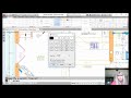
On the Status bar, expand the Customization menu and choose Infer Constraints to add this tool to the Status bar. Then, click in a blank spot in the drawing to close the menu. Now that the Infer Constraint button has been added to the Status bar, you can click this button to toggle Infer Constraints on and off. Toggle on Infer Constraints.
Once you enable Inferred Constraints, AutoCAD will automatically add geometric constraints as you create or modify objects in your drawing. Use the Rectangle tool in the ribbon to create a new rectangle. With Infer Constraints toggled on, AutoCAD automatically adds the appropriate constraints to the rectangle. Now, when you drag a corner of the rectangle, the rectangle retains its intended shape.
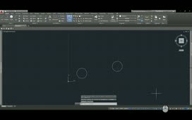
With Infer Constraints toggled on, AutoCAD also applies geometric constraints whenever you use object snaps as you create or modify the geometry. For example, use the Circle tool to create a circle and snap its center point to the midpoint of the bottom line of the rectangle. Then, select the rectangle and click and drag the grip in the lower-right corner. The center of the circle remains at the midpoint of that side of the rectangle.
Select the grip in the middle of the bottom edge of the circle and drag that grip to move it. The circle moves along with the rectangle.
Press ESC. Then, select the circle and click and drag its center grip. The rectangle changes size so that the midpoint of its bottom edge remains attached to the circle.
Use the Line tool to create a line to the left of the rectangle at any random angle. Then, start the LINE command again, press SHIFT and right-click to display the Object Snap Override shortcut menu. Choose Perpendicular, and then create a second line perpendicular to the first. End the command, click to select the first line, and then click the grip at the top end of the line. When you move this grip to change the alignment of the line, the second line moves so that it remains perpendicular.
Start the LINE command again and draw a line parallel to the first line. With Infer Constraints toggled on, AutoCAD automatically applies a parallel constraint.
Start the LINE command again and draw a line tangent to the circle. AutoCAD automatically applies a tangent constraint.
When Inferred Constraints is toggled on, the program also automatically applies coincident constraints for Endpoint, Midpoint, Center, Node, and Insertion object snaps. Start the CIRCLE command, choose the Nearest object snap override, and snap the center of the circle to the top edge of the rectangle. Then, select the circle. AutoCAD has applied a coincident constraint between the center of the circle and the line. When you select the circle and drag its center grip, the circle remains aligned or coincident with the top edge of the rectangle. When you drag the circle up, the rectangle moves so that its top edge remains coincident with the center of the circle.
Inferred constraints are also created when you use the FILLET command. On the Home ribbon, in the Modify panel, click the Fillet tool. Right-click, choose the Radius option, and enter a radius of 2.5 units. Then, click to add a fillet to the upper-right corner of the rectangle. AutoCAD automatically adds a pair of tangent constraints.
Inferred constraints is a very powerful feature.
Source: Autodesk