Adjusting Orthographic Views with Solid Drawing
After you create a three-dimensional part, you may need to create two-dimensional orthographic views of the 3D model in order to produce working drawings. There are a number of ways to do this in AutoCAD.
One of the methods uses three related tools: Solid View, Solid Drawing, and Solid Profile. To find these tools, on the Home ribbon, expand the Modeling panel. These tools help you do the work necessary to draw 2D representations of solids that mimic conventional 2D drafting. And these three tools are meant to be used in the order in which they appear in the Modeling panel. Expand and pin this panel open if it is not already open.
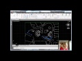
In the exercise file, the various views of the model have been arranged on a paper space layout using the Solid View tool. These views still display the actual 3D model, and use whatever visual style was in effect when you created the views. You are now ready to convert them into two-dimensional orthographic projections by using the Solid Drawing tool.
In the expanded Modeling panel, click the Solid Drawing tool. The program prompts you to select objects, and you can use any convenient object selection method. For example, use a crossing window to select all four viewports, and then press ENTER or right-click.
The program immediately processes the viewports, converting the three-dimensional model into two-dimensional representations.
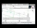
When you expand the Layer Properties Manager palette, you can see that the program has created new layer names based on the names of the various views that had been created previously using the Solid View tool. For example, you can see several layers that begin with the name “Front”, another set of layers that begin with the name “Section”, another set that begin with the name “Side”, and so on. Then, within each group of layers, the program has created a layer for dimensions, a layer for hidden lines, a layer for visible lines, and so on. And for the section view, it has also created a layer for the hatch pattern applied to the cross section. The viewports have also been placed on their own layer. You can then use the tools in the Layer Properties Manager to change any of the layer settings-such as colors, linetypes, lineweights, and so on, as needed.
Source: Autodesk