Do you need to bring PDF data into AutoCAD?
If you read my last post, you know how easy it is to convert vector‐based PDF files to DWG format using the PDF Import functionality in AutoCAD 2017. While AutoCAD 2017 offers the most efficient method for importing PDF data, it doesn’t work with all PDF files. If the PDF file is raster‐based instead of vector‐based, for example, PDF Import is not an option because the necessary vector data doesn’t exist in the PDF file. Check out my previous post for tips on identifying vector‐ vs raster‐based PDF files. If you want to reuse data from a raster‐based PDF file, tracing is your best option. Fortunately, there are tools that make tracing the PDF (and other raster‐based files) much easier. Let me introduce you to AutoCAD Raster Design!
AutoCAD Raster Design is an application that is built on top of AutoCAD. Prior to using AutoCAD Raster Design, I spent countless hours manually tracing geometry in AutoCAD from attached raster files. It wasn’t hard, but it was monotonous and time-consuming. I knew there had to be a better way! I downloaded a free trial of AutoCAD Raster Design and other products that are available in the Architecture, Engineering, and Construction collection. After using the trial software for 30 days, I put together a white paper for management to review the many features I used to be more productive. It must have been convincing because I’ve been enjoying my subscription with access to AutoCAD Raster Design ever since! There’s a wide variety of ways to use the software. I’ll share just a few of my favorites to help you more efficiently redraw geometry from a raster-based PDF file.
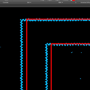
In this example, I am redrawing an architectural background as well as piping and electrical information that is associated with the design I’m working on. It can be extremely challenging to redraw a building from an image that is skewed because of a poor-quality scan. Lines that are supposed to be straight are wavy and misaligned. Fortunately, AutoCAD Raster Design includes image correcting commands that will increase the quality of a redraw. In the left image below, notice the straight polylines with the misaligned image underneath. On the right image, I have straightened the image lines to align with the polyline using Raster Design.
Contents
Converting PDF to TIF
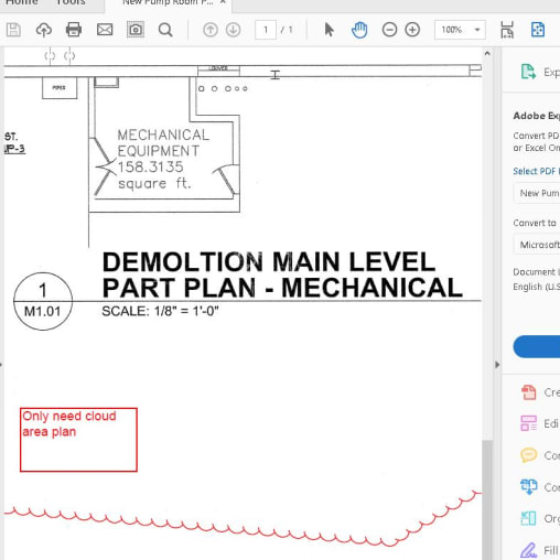
The Raster Design software will only recognize raster image files as opposed to PDF files. So the first step in this process is to convert the PDF to an image file. I open the PDF in Adobe Acrobat and save-as a TIFF. In this example, I converted a PDF I received from a client.
It is also important to check the scale of the drawing being redrawn. Take a note of it, you will have the option to specify the correct scale when you insert the image as a reference to the drawing.
Referencing the Image to the Drawing
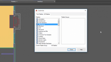
Once you have the right file format, launch Raster Design, either from a desktop icon or through the Apps Menu. Or click the tab if the Raster Design Ribbon tab is already loaded within the AutoCAD application you’re currently using. (You’ll see a Raster Tools ribbon tab along with your familiar default AutoCAD ribbon tabs). As you can see from the image below, there are many tools. In this example, we’ll be using just a few of my favorites!

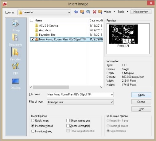
Use the insert image command located on the Raster Design Ribbon. It’s important to use the Raster Design command for this task. If you don’t, Raster Design tools will not be associated with the image. After selecting the image you want to attach, ensure you choose Insertion Wizard as your insertion option. It will lead you through the important steps.
After choosing Open you will be presented with the “modify correlation Values” dialog box. Enter the scale you determined earlier. In the example below, I have entered 96 as the scale factor. Proceed through the menus by hitting next until the image is inserted into the drawing.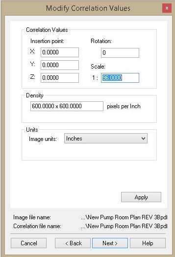
Creating Construction Geometry
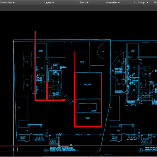
Now that the image is referenced, I may have to rotate slightly to get the image aligned to the X, Y axis. I then find the longest straight line geometry for the redraw, and draw orthogonal construction lines to assess the imperfections and establish some orthographic geometry. In the example below, I chose the outside of the building to draw some orthographic lines. The idea here is to start the lines in the exact location of the corners and draw 90 degree angles straight up and down from the start point.
Fixing the Raster Image
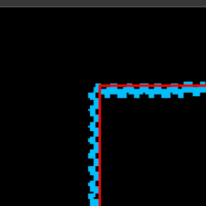
The imperfections on the raster image are subtle when zoomed out as in the image above. But when zoomed in you can see the raster image lines are not straight. The images below show opposing ends of the same lines. In the left image, I am showing the point in which I chose to start my straight lines from. This is where the geometry will line up with the referenced image. In the right image, you’ll see the other side of the same line. This is where the image veers off from the straight line.
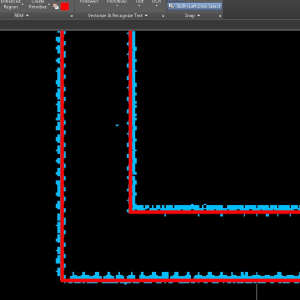
Rubber Sheet Command–Step 1
Now that we have some orthogonal lines for reference, we’ll use the rubber sheet tool. It allows you to manually match points on the skewed image with their corresponding points on the orthogonal AutoCAD geometry. Choose Rubber Sheet from the Raster Tools ribbon tab and select the polynomial option. Then choose Add Points and start clicking on the drawing.
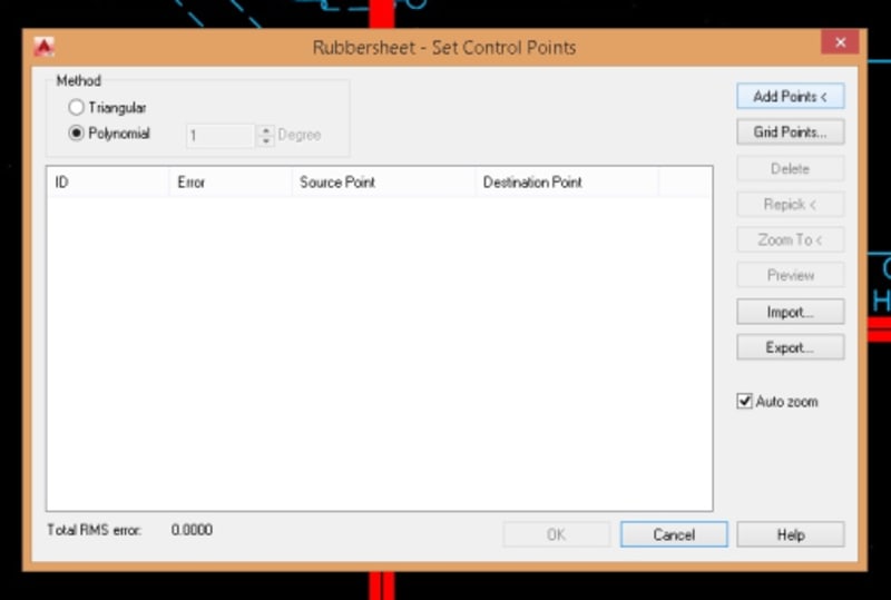
Rubber Sheet Command–Step 2
The first point you click will be where the image file is off. The second click is where the image file should be aligned to. You can do this to a few places or a multitude of places. This process might look familiar to you if you ever use the AutoCAD Align command! I would say that is exactly what the rubber sheet is doing. It is aligning the image to the desired geometry.

Rubber Sheet Command–Step 3
Once you’ve picked the most appropriate source and destination point combinations, choose OK to view the results. This command will work mainly in the areas where you are selecting points. If you find that the image needs more adjustments, repeat the commands and adjust to your heart’s content.
Rubber Sheet command–Step 4
You can do a few and then do a few more, molding the drawing to align to the orthographic line you laid out in the previous steps. Each time you complete the command the program will save the image file.

When I’m satisfied that the drawing is orthographic enough, I proceed with drafting out the remainder of the details and inner workings of the drawing.
There you have it: a step-by-step process using the Rubber Sheet command inside the software to true up skewed geometry and leap over the hurdle of recreating poorly captured geometry.
The Rubber Sheet tool is one of my favorite Raster Design tools but there are many others to make tracing data from raster files easier. Check out this tutorial to learn more!
Source: Autodesk