While it’s always exciting to push limits, this time, we’re going to do this literally with the AutoCAD LIMITS command.
Contents
AutoCAD Grid Limits
When the Limits feature was first introduced, its primary purpose was to enforce a boundary for the drawing area and to define a plotting area. With the advent of paper space layouts, that role was diminished for many users. But there’s still an incredibly useful interaction between the Limits feature and the grid display in the drawing area.
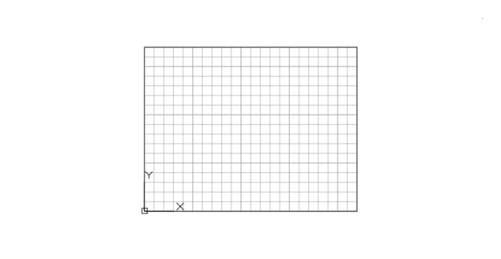
Currently, turning on the grid for the entire drawing area is a little overwhelming when I just want to work within an area as represented by the rectangle below.
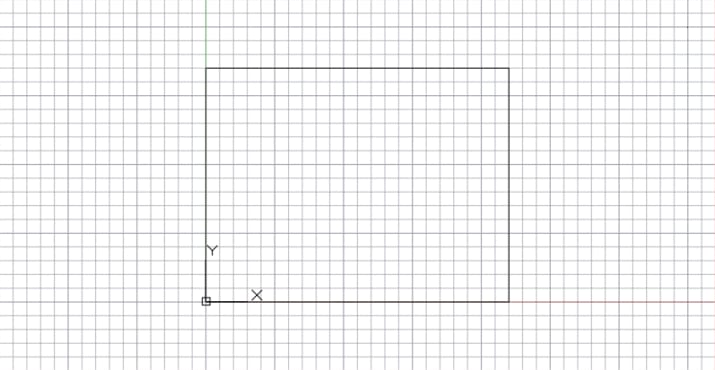
However, when I set the limits to the opposite corners of the rectangle, and then set the GRIDDISPLAY system variable to 2, I get a fixed grid completely contained within the limits as shown here.
Incidentally, setting GRIDDISPLAY to 4 displays an adaptive grid that changes as you zoom in or out if that’s your preference.
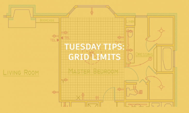
To move the grid to a different part of your drawing, you can either redefine the limits or move the User Coordinate System (UCS). For example, you might want to display the grid only in a portion of a drawing such as in the floor plan shown here.
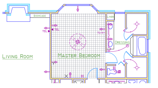
My general recommendation is to move the UCS, which ensures precise grid alignment, facilitates entering smaller coordinate values, and also provides a way to rotate the grid.
Tip: Always set the desired limits when the UCS is coincident with the World Coordinate System (WCS) and use the origin point (0,0,0) as one corner of the limits before moving the UCS.
But does the Limits feature work in 3D as well?
Glad you asked! Here’s what a grid looks like in a 3D view with perspective turned on:
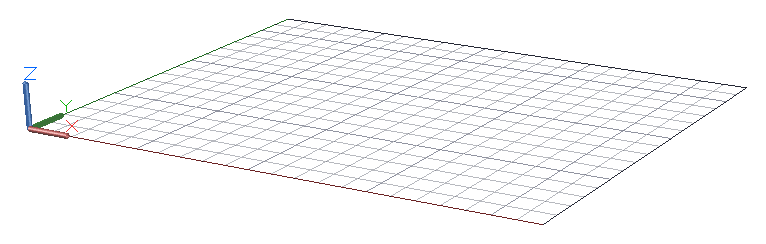
When I model in 3D, I get vertigo if I don’t limit the area covered by the grid. When the grid display is limited, it serves as a handy visual cue for the location of the construction plane, the XY plane of the UCS as shown.

However, note that the LIMITS command was originally created for 2D only, so it cannot be defined or redefined in a 3D context. The key is to first set the limits when the UCS is coincident with the World Coordinate System. This means that the UCS overlaps the WCS exactly, which is its initial position. Entering UCS and pressing Enter twice realigns the UCS with the WCS.
The same procedure also works for the Isodraft feature. Changing the Isoplane automatically reorients the grid, and relocating the UCS Origin determines the apparent depth of the grid plane.

So in summary, the steps are as follows:
- Make sure that the UCS is coincident with the WCS. Enter UCS and press [Enter] twice.
- Turn on the grid [F7] and set the grid spacing with the GRID command.
- Enter LIMITS and set one corner to 0,0 followed by a second 2D point such as 8,5 or whatever.
- Enter GRIDLIMITS and set it to 2 or 4.
- Locate or reorient the UCS as needed.
So, give it a shot and see whether pushing AutoCAD limits is useful for your work!
More on Grids and Grid Limits
LIMITS (Command)
GRIDDISPLAY (System Variable)
About Adjusting the Grid and Grid Snap
About the User Coordinate System (UCS)
More Tuesday Tips
Come back next week for some tips on XREFs from Lynn, and don’t forget to check out the full Tuesday Tips With Lynn series in the meantime.
Source: Autodesk