When working with AutoCAD, there are certain CAD terms you should know. In this second of the two-part “Beginner’s Guide for CAD Terms” series, we will explore some of the most important computer-aided design terms for geometry and object editing.
This AutoCAD glossary can help with basic CAD terminology you should know when it comes to geometry and editing. When we talk about geometry we are referring to the objects that make up your drawings and designs as well as the features they contain or rely on. The editing terms refer to object selection methods and graphical features.
Note that all definitions are based on the Windows operating system and are focused on 2D drafting and design. Links for CAD terms provide deeper information to learn more.
Contents
AutoCAD Glossary – Geometry
Annotations: Text, dimensions, tolerances, symbols, notes, and other types of explanatory symbols or objects.
Annotative: An object property that is assigned to objects that are used to annotate drawings. This property automates the process of scaling annotations in layout viewports and in model space. Annotative objects are defined at a paper height.
Annotation Scale: A setting that is saved with model space, layout viewports, and model views. When you create annotative objects, they are scaled based on the current annotation scale setting and automatically displayed in a view at the correct size.
Anonymous Block: An unnamed block created by several features, including associative and nonassociative dimensions.
Associative Dimension: A dimension that automatically adjusts its size and value when the associated geometry is modified.
Attribute: An object that is included in a block definition to store alphanumeric data. Attribute values can be predefined, or they can be specified when the block is inserted. Attribute data can be extracted from a drawing and saved to a text file.
Attribute Tag: The identifying name given to an attribute, which is used during extraction of attribute data from a drawing.
Attribute Value: The text or numeric information stored in an attribute.
Base Point
1. In the context of editing grips, the grip that changes to a solid color when selected to specify the focus of the subsequent editing operation.
2. A point for relative distance and angle when copying, moving, and rotating objects.
3. The insertion base point of the current drawing.
4. The insertion base point for a block definition.
Block: A generic term for one or more objects that are combined to create a single named object.
Block Definition: The name, base point, and set of objects that are combined and stored in the block definition table of a drawing.
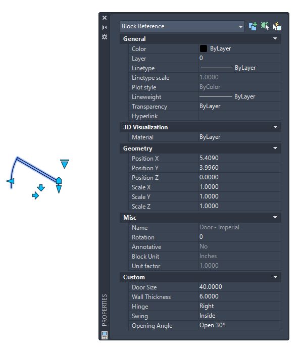
Block Instance: A named compound object that is inserted in a drawing and displays the data stored in a block definition.
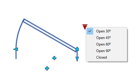
Dynamic Block: Dynamic blocks contain rules and restrictions that control the appearance and behavior of a block when it is inserted into a drawing or when it’s later modified. You can add these rules and controls to any existing block as well as using them when you create new blocks. The controls are limited to 2D operations only.
Construction Line: Temporary linework entities that can be used as references when creating and positioning other objects or linework. These lines can be Xlines or Rays.
Coordinates:
Absolute Coordinates: Coordinate values measured relative to the coordinate system’s origin point (0,0,0).
Cartesian Coordinates: A coordinate system where the X, Y, and Z axes meet at 0,0,0.
Relative Coordinates: Coordinates specified in relation to previous coordinates.
Custom Object: A type of object that is created by an ObjectARX application and that typically has more specialized capabilities than standard objects. Custom objects include parametric solids (Mechanical toolset), intelligently interactive door symbols (Architecture toolset), polygon objects (Map 3D toolset), and associative dimension objects (AutoCAD and AutoCAD LT).
Dimension: A graphical object indicating on a drawing, the sizes of the object and the other details essential for its construction and function. The basic types of dimensions are Linear, Radial, Angular, Ordinate, and Arc Length.
Dimension Style: A named group of dimension settings that determines the appearance of the dimension and simplifies the setting of dimension system variables.
Definition Point AKA Defpoint: A node located at the end of an extension line corresponding to the location on the object being dimensioned. Definition points, also called defpoints, are stored on the reserved, non-plotting Defpoints layer.
Explode: To disassemble a complex object, such as a block, dimension, solid, or polyline, into simpler objects. In the case of a block, the block definition is unchanged. The block reference is replaced by the components of the block.
Field: A specialized text object set up to display data that may change during the life cycle of the drawing. When the field is updated, the latest value of the field is displayed.
Fill: A solid color covering an area bounded by lines or curves.
Font: A character set, made up of letters, numbers, punctuation marks, and symbols of a distinctive proportion and design. AutoCAD uses either its proprietary, legacy fonts which are Shape Files compiled into SHX files, or TrueType Fonts, commonly referred to as TTF.
Hatch, Associative: Hatching that conforms to its bounding objects such that modifying the bounding objects automatically adjusts the hatch.
Island: An enclosed area within another enclosed area. Islands may be detected as part of the process of creating hatches, polylines, and regions.
Layer: A logical grouping of data that are like transparent acetate overlays on a drawing. You can view layers individually or in combination. Layer properties include On / Off, Freeze / Thaw, Lock / Unlock, Plot, Color, Linetype, Lineweight, Transparency, and Description.
Named Object: Describes the various types of nongraphical information, such as styles and definitions, stored with a drawing. Named objects include linetypes, layers, dimension styles, text styles, block definitions, layouts, views, and viewport configurations. Named objects are stored in definition (symbol) tables.
Node: A type of object snap that locates point objects, dimension definition points, and text origin points.
Object: One or more graphical elements, such as text, dimensions, lines, circles, or polylines, treated as a single element for creation, manipulation, and modification.
Object Enabler: A tool that provides specific viewing and standard editing access to a custom object when the ObjectARX application that created the custom object is not present. Available only for AutoCAD-based products.
OLE: For object linking and embedding. An information-sharing method in which data from a source document can be linked to or embedded in a destination document. Selecting the data in the destination document opens the source application so that the data can be edited.
Origin: The point where coordinate axes intersect. For example, the origin of a Cartesian coordinate system is where the X, Y, and Z axes meet at 0,0,0.
Parametric Drawing: A feature that assigns constraints to objects, establishing the distance, location, and orientation of objects with respect to other objects.
Properties: Properties that are common between a selection of objects. These include color, layer, linetype, linetype scale, plot style, lineweight, transparency, hyperlink, and thickness.
Point:
1. A location in 3D space specified by X, Y, and Z coordinate values.
2. An object consisting of a single coordinate location.
Polyline: An object composed of one or more connected line segments or circular arcs treated as a single object. Also called pline.
Proxy Object: A substitute for a custom object when the ObjectARX application that created the custom object is not available.
Regenerate: To update the objects in the drawing area by recomputing the screen coordinates from the database.
Table: A rectangular array of cells that contain annotation, primarily text but also blocks. In the AEC industry, a table is often referred to as a “schedules” and it contains information about the materials needed for the construction of the building being designed.
Table Style: A style that contains a specific table format and structure. A table style contains at least 3 cell styles.
Text: The generic term for textual annotations in a drawing. Text can be defined as either Multiline Text (MTEXT) or Single Line Text (TEXT or DTEXT for Dynamic Text).
Text Style: A named, saved collection of settings that determines the appearance of text characters—for example, stretched, compressed, oblique, mirrored, or set in a vertical column.
Underlay: An Autodesk DWF that is attached to a DWG drawing file to provide visual information and object snap locations.
Vector: A mathematical expression with precise direction and magnitude (length) but without a specific location.
Vertex: A location where edges or polyline segments meet.
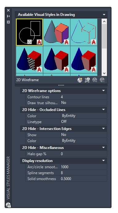
Visual Style: A collection of settings that control the display of edges and shading in a viewport.
Wipeout: A polygonal area that masks underlying objects with the current background color. This area is bounded by the wipeout frame, which you can turn on for editing and turn off for printing or plotting.
Xref – External Reference: A file referenced from a drawing file. An external reference is a link to the referenced file. Supported external references include the following file types: DWG, raster images, DWF, DWFx, DGN, PDF.
AutoCAD Glossary – Editing
Aperture: The size of the object snap target box. Initial value is set to 10.
Fence: A multiple object selection method that allows the user to create a free-form line by dragging the cursor over objects. Any object the fence touches is selected.
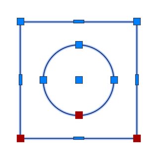
Grips: Small squares and triangles that appear on objects that you select. After selecting the grip, you can edit the object by clicking or right clicking the grip instead of entering commands.
Hot Grip: A selected or activated grip.
Lasso: A multiple object selection method that allows the user to create a non-orthogonal (free-form) window or crossing area.
Pickbox: The size of the visible object selection target box at the center of the crosshairs.
Rubber Band: A line that stretches dynamically within the drawing area with the movement of the cursor. Typically, one endpoint of the rubber-band line is attached to a point in your drawing, and the other endpoint is attached to the moving cursor.
Selection, Crossing: A rectangular multiple object selection method drawn to select objects fully or partly within its borders.
Selection, Window: A rectangular multiple object selection method drawn to select objects fully within its borders.
Tracking: A method for determining a point relative to other points on the drawing, such as Polar or Object Snap tracking.
Source: Autodesk