The AutoCAD OFFSET command has been around for a long time. No doubt, you’re familiar with two tried-and-true methods of creating a new entity with Offset.
You can select a through point or specify a distance and direction. Even new users can probably say they’ve done it thousands of times.
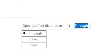
But, over time, there have been a few options added to the command that often get overlooked.
Contents
Erase
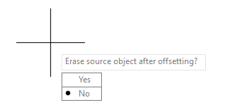
The first option is Erase. Selecting this will bring up a secondary prompt, which will allow you to specify whether the source object with be erased after the offset is made. It defaults to No, but your workflow may be such that you want to erase it. Set it to Yes and eliminate an extra step after your Offset.
Layer
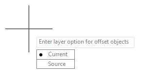
The next option is Layer. Again, you’ll get a second prompt that gives you two options for the newly created offset object. You can leave it on the default setting of Source, which will use the layer that the original object is on, or you can choose to place the new object onto the current layer.
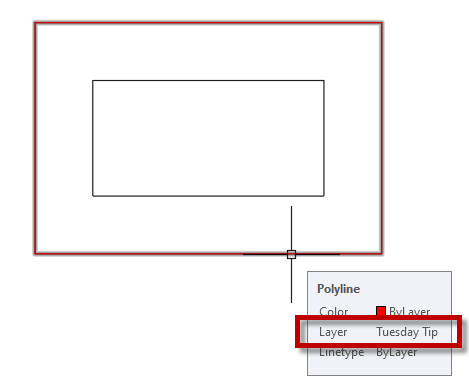
Here we see the result of applying our offset to the current layer, Tuesday Tip (red).
Options With System Variables
AutoCAD uses a couple of System Variables to keep track of your Offset choices. One is OFFSETDIST, which stores the value you enter at the Distance prompt. Interestingly, this is also the mechanism it uses to know if you want a Distance or Through offset. If its value is negative (e.g., -1.00), it uses the Through option. A positive value uses Distance.
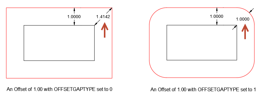
There is another SysVar that is really interesting. It is named OFFSETGAPTYPE. By default, it is set to 0 (zero), which produces the normal type of offset that we all know and love.
But there are two other settings possible for this variable, and they’ll greatly affect how the offset appears. Quoting the Help file, a value of 1 “Fillets line segments at their projected intersections. The radius of each arc segment is equal to the offset distance.”
In other words, it maintains the desired distance (or through point) at corners. It’s easier to see an example of how it works it:
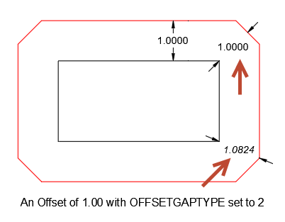
You can specify a value of 3 to use Chamfers instead of Fillets. I offer this with the following caveat though: If you require a uniform distance away from the original object, use the Fillet option (value = 1) as the Chamfer version is accurate only at the point perpendicular to the corner of the original object.
Finally, note that the value of OFFSETGAPTYPE is stored in the registry, so it will apply to all drawings until changed.
Last Thoughts
As we’ve seen, AutoCAD Offset is more than just Distance and Through.
As always, I encourage you to dig a little deeper into your favorite AutoCAD commands. Keep an eye on the Command Line for options you may not know about, or search through the Express Tool’s System Variable Editor for variables you’re not aware of.
More Tuesday Tips
Check out our whole Tuesday Tips series for ideas on how to make AutoCAD work for you. Do you have any favorite AutoCAD tips? Tell us in the comments!
Source: Autodesk